
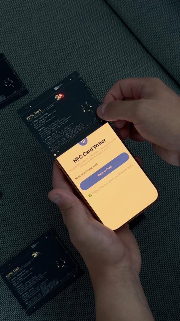
Every battery you design out of a board is one you never have to replace, glue in, or explain to a customer. Kevin Tang’s PCB business card makes that point in about two seconds: tap it to a phone and the LEDs light up, with no coin cell anywhere on the board. The card shares his contact details over NFC at the same time, but the glow is the part that makes people turn it over looking for the battery.
What the card actually is
It is a standard business-card-sized PCB with an NFC chip, a copper antenna traced around the board edge, and a few LEDs. There is no regulator, no boost converter, and no storage capacitor doing anything clever. The phone supplies all of the energy, and the card is dark again the moment you pull the phone away.
Where the power comes from
An NFC reader is not a passive listener. It broadcasts a 13.56 MHz field specifically to power the tag it is talking to, because ordinary NFC stickers have no battery either. The chip rectifies that field, wakes up, answers, and goes quiet. What most people never notice is that some NFC chips expose the surplus on a pin. NXP’s NTAG I²C Plus family routes harvested energy to a VOUT pin, and the datasheet quotes roughly 5 mA at 2 V under one test setup. That is a tiny budget. It is also enough for two red LEDs at a couple of milliamps each, or a sensor reading, or a microcontroller wake pulse measured in milliseconds.
The catch is coupling. Harvested current falls off fast with distance and antenna mismatch, so the number on the datasheet is a best case, not a promise. Antenna geometry and the tuning capacitor across it decide whether you get 5 mA or 1 mA.
Build one yourself
- An NTAG I²C Plus chip (NT3H2111 or NT3H2211) for the VOUT pin. A plain NTAG 213 will not do this.
- A spiral antenna on the top copper layer, plus a tuning cap sized to land the resonance near 13.56 MHz.
- Low-current LEDs. Red parts around 1.9 V forward voltage leave the most headroom; blue and white at 3 V will barely flicker.
- Series resistors, and 0.8 mm board thickness so the card does not feel like a coaster.
The gotcha that bites first is the I²C side: if you add a microcontroller to write the tag’s memory over SDA and SCL, you still need pull-ups, and the chip arbitrates between the RF field and the I²C bus rather than serving both at once. Prototype the logic on a breadboard with a dev board first, then commit to the card layout once the memory writes are behaving. Kevin’s full write-up, including the measurements, is at kevin.md.
Frequently Asked Questions
How does the card light up with no battery?
The phone broadcasts a 13.56 MHz field to power the NFC tag. An NTAG I2C Plus chip passes the surplus out on a VOUT pin, roughly 5 mA at 2 V, which is enough to drive a couple of low-current LEDs for as long as the phone is held against the card.
Can I use any NFC chip for this?
No. You need a chip with an energy-harvesting output, such as NXP’s NTAG I2C Plus (NT3H2111/NT3H2211) or NTAG 5. Common tags like the NTAG 213 found in cheap NFC stickers have no VOUT pin, so there is nothing to drive the LEDs with.
What will I learn if I build this?
Antenna design and RF tuning, which most hobby projects never touch: you size a tuning capacitor to bring a spiral trace into resonance at 13.56 MHz. You also get practice reading a power budget off a datasheet, picking LEDs by forward voltage, and wiring an I2C bus with proper pull-ups. It makes a strong portfolio piece for an ECE thesis or a job hunt, since you hand the interviewer the board itself.
