
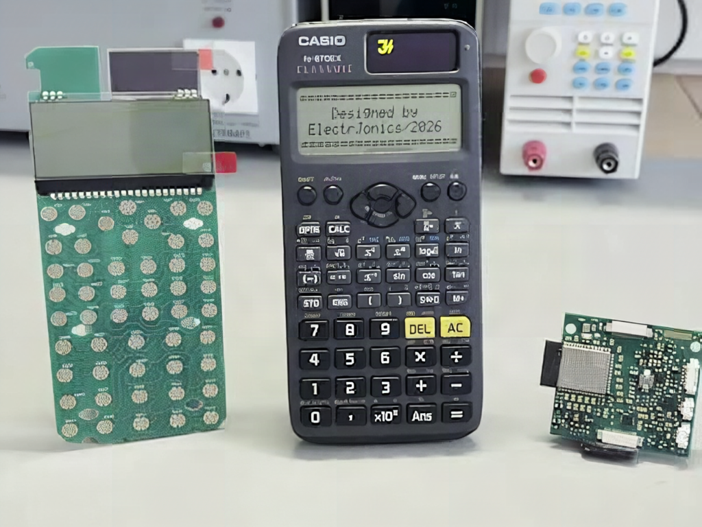
A calculator only helps if you already know which keys to press. Jonas of the ElectrJonics YouTube channel built one that takes a photo of a handwritten equation and works it out for you, which is the kind of tool a struggling Grade 11 physics student would actually use. Hackster covered the second version, and it is open source.
What changed in V2
The first model proved an AI could live inside a handheld calculator, but the hardware left no room to grow. Instead of patching it, Jonas started over with a new schematic, custom PCBs, and a new enclosure. V2 adds a camera for reading equations or printed text, and it has 2 displays: one for the calculator interface and a second for status messages and longer AI answers.
How the electronics fit together
An ESP32 does the work. Its Wi-Fi sends questions to cloud models through the OpenAI API, and smaller models can run locally on the chip, though a dual-core 240 MHz microcontroller with limited RAM caps what they can do. The boards are modular: processor, displays, and keypad sit on separate PCBs, so you can swap a screen without redrawing the whole design. Custom ESP32 firmware handles the keypad scan, camera capture, display updates, and network calls.
The gotcha with any camera-plus-display ESP32 build is pin budget. A camera module eats a big share of the available GPIO, so a second display usually goes on I2C, which means 4.7k ohm pull-up resistors on SDA and SCL and a 3.3 V supply that can handle the camera’s current spikes.
Build it yourself
Start smaller than V2. Wire an ESP32 to one I2C OLED on the default SDA and SCL pins, add a 4×4 keypad, and send typed questions to a cloud model over Wi-Fi. Add the camera once the text path works. ESP32 boards, OLED modules, and keypads are available at circuit.rocks, and the full build details are on the source page. For a thesis or capstone, comparing local versus cloud answers on the same math problems makes a solid experiment.
Frequently Asked Questions
What microcontroller powers the AI calculator?
An ESP32. Its built-in Wi-Fi reaches cloud AI services through an API, and its firmware also runs the keypad, camera, and both displays. Small models can run locally, within the chip’s memory limits.
Why does the V2 design use separate PCBs?
Splitting the processor, displays, and keypad onto modular boards lets the maker upgrade one part without redesigning the whole calculator, which the first version’s cramped hardware could not do.
What will I learn if I build this?
You will practice ESP32 firmware, keypad scanning, I2C display wiring, camera interfacing, calling a web API over Wi-Fi, and basic PCB layout. It also teaches the trade-offs between local and cloud AI inference.
