
Set aside a Saturday and one small breakout board, and a project that has been stuck on your bench for months can finally move. The blocker is almost always the same: your microcontroller speaks I2C fine, but every DAC in the drawer tops out at whatever rail feeds it, usually 3.3V or 5V. Anything wanting a 0-10V control signal, a fan driver, a lab supply set point, an op-amp bias, sits there unfinished.
The board that fixes it
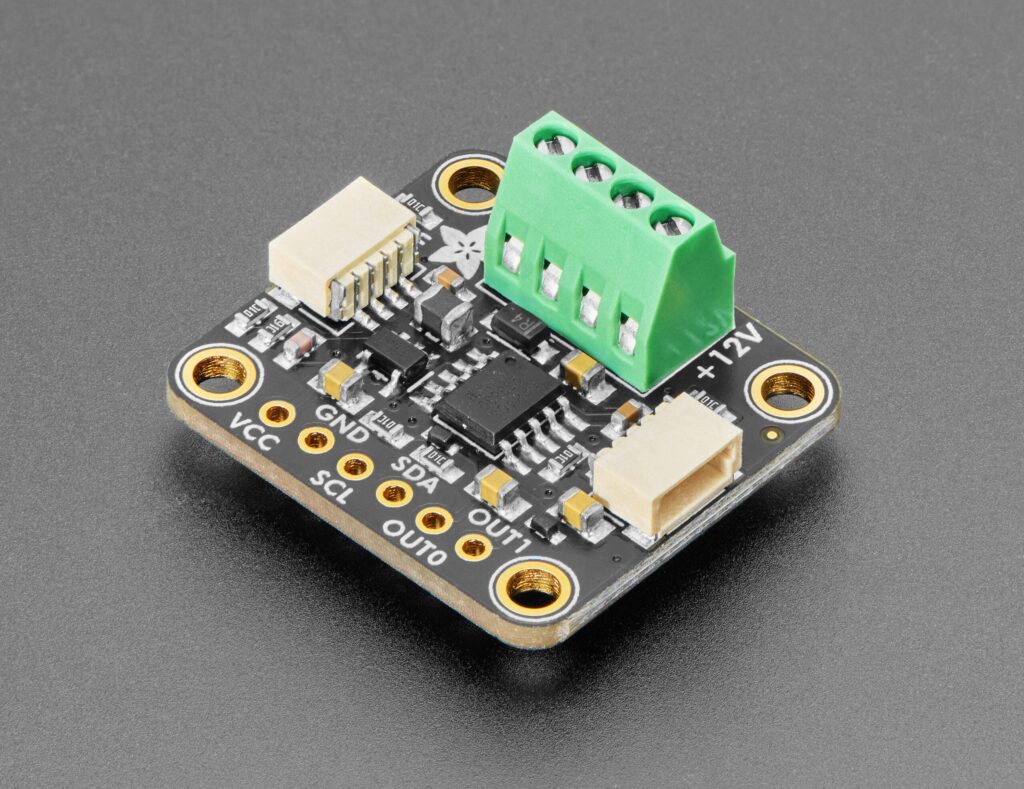
Adafruit’s new GP8403 breakout is built around the GP8402, a 12-bit I2C-to-analog converter. Write a value between 0x000 and 0xFFF and it drives two independent outputs, switchable between 0-5V and 0-10V, at a quoted output voltage error of 0.2%. An on-board DC/DC booster makes the high rail, and that 12V line is broken out to a pad where you can draw up to 100mA to run something external.
Three solder jumpers on the back (A0, A1, A2) set the I2C address, so eight boards can share one bus for 16 analog channels. The logic side accepts 3.3V or 5V and is kept separate from the boosted output stage, so a Pico and an UNO both talk to it without level shifting. STEMMA QT / Qwiic connectors are on board, plus a 4-pin 2.5mm terminal block and a strip of 0.1″ header for breadboard work.
Parts and the real cost of the afternoon
- The GP8403 breakout itself
- Any I2C host you already own: Arduino UNO, Raspberry Pi, Pico, or an ESP32
- A STEMMA QT cable, or four jumper wires to SDA, SCL, power and ground
- A multimeter, because you will want to confirm the output really swings to 10V
Two gotchas worth knowing before you start. The outputs carry 10uF caps per the datasheet, so settling is slow. This part is for bias and set-point work, not for synthesising fast waveforms. And the non-volatile memory feature, which lets the chip boot back into its last voltage, is driven by bit-banging the I2C lines. Adafruit got it working on an ATmega328, but plenty of platforms will not hand over their I2C pins, so test that on your own hardware rather than assuming it.
Arduino and CircuitPython libraries ship with it, so the first output takes maybe ten minutes of code. Read the full product write-up at Adafruit, then spend Sunday wiring one channel to that variable-speed fan you gave up on.
Frequently Asked Questions
How does the GP8403 reach 10V when the microcontroller only supplies 5V?
The board carries its own small DC/DC booster that generates a 12V rail from the logic supply. The GP8402 chip then converts your 12-bit I2C value into an analog output on that boosted rail, so you get a genuine 0-10V swing from a 3.3V or 5V host. The 12V rail is also broken out, and you can pull up to 100mA from it for external circuitry.
What do I need besides the board, and are there limits I should plan around?
An I2C host such as an Arduino UNO, Raspberry Pi, Pico or ESP32, plus a STEMMA QT cable or four jumper wires to SDA, SCL, power and ground. A multimeter helps you verify the swing. The main limit is speed: 10uF capacitors on the outputs mean slow settling, so treat it as a set-point and bias part rather than a waveform generator. The non-volatile memory mode relies on bit-banging I2C and does not work on every platform.
What will I learn if I build this?
You will get hands-on with I2C addressing, since the A0, A1 and A2 jumpers let you chain eight boards onto one bus for 16 channels, which is exactly the addressing logic that trips up most students the first time. You also practise reading a datasheet for its constraints rather than its headline numbers, mapping a 12-bit digital range onto a real analog voltage, and measuring the result to check your code against the physical world. That digital-to-analog conversion path shows up constantly in instrumentation and control coursework.
