
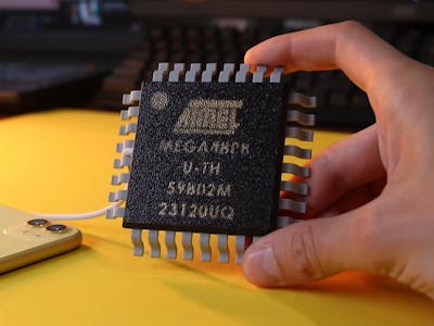
Scroll through maker YouTube lately and you keep hitting the same itch: take something tiny and iconic, blow it up to desk-sculpture scale, and make the giant version actually do a job. Oversized keyboards, room-sized 555 timers, and now a chunky ATmega package you can drop your phone onto. Nick Electronics landed squarely in that lane by turning the microcontroller every Arduino tinkerer cut their teeth on into a working Qi wireless charger.
The build itself
Nick worked through three versions before he was happy. Attempt one was the shortcut: gut a commercial wireless charger and drop its guts into an enclosure shaped like an ATmega chip. Even that fought back. Charging efficiency falls off fast as the coil-to-phone gap grows, so the top wall had to be printed almost paper-thin, and laser-engraving the chip markings just melted the surface. So he went the hard way and designed the charging hardware himself: a custom PCB carrying a microcontroller, a MOSFET-based inverter, a resonant LC tank, and a USB-C power input on the transmitter, plus a matching receiver board with its own coil, bridge rectifier, and buck converter.
Why the homemade transmitter cooked itself
The DIY transmitter proved the physics, high-frequency switching throws an alternating magnetic field that induces current in the receiver coil, but it also showed why real chargers cost what they do. There is no communication layer in a bare LC tank. Without the handshake the Qi standard uses to sense a phone and throttle power, the transmitter kept dumping energy into the circuit with nothing on top. Voltage across the inductor climbed hard off a modest 5-volt input, parts crept toward 90°C, and the heat was enough to soften the plastic housing. The shipping version quietly swapped in a Qi-certified module for safe charging, while multi-material printing embedded crisp white lettering into black plastic for that authentic die look.
What to try next
You do not need to fake a phone charger to learn from this one. Wire up a single transmit and receive coil pair on a breadboard, drive it with a signal generator, and watch how coupling drops the instant you widen the gap by a few millimeters, that is the whole game behind Qi alignment. If you want the resonant-inverter side, a MOSFET half-bridge and an LC tank is a tidy weekend bench project, just add a thermal cutoff so you do not repeat the 90°C mistake. Full teardown and build notes are on Hackster: https://www.hackster.io/news/this-giant-atmega-chip-won-t-run-code-but-it-will-charge-your-phone-30ba2e5f2bda
Frequently Asked Questions
How does the giant ATmega chip charge a phone?
The final build hides a Qi-certified wireless charging module inside a 3D-printed ATmega-shaped enclosure, so it charges any Qi phone safely while looking like an oversized microcontroller.
Why did the DIY wireless transmitter overheat?
A bare resonant LC tank has no Qi communication layer, so it kept pumping energy in with no phone present. Inductor voltage climbed off a 5-volt input and parts hit around 90 degrees C, enough to soften the plastic.
What will I learn if I build this?
You will pick up resonant power basics, MOSFET inverter and LC tank design, PCB layout for a transmitter and receiver pair, buck converter and rectifier wiring, and why coil alignment and thermal limits matter in wireless power.
