
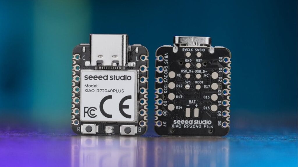
Running out of pins is the quiet reason a lot of XIAO projects stall halfway. You wire a sensor node onto a board the size of a postage stamp, then realise you still need a second I2C bus, an analog input for the battery divider, and somewhere to hang a status LED. Seeed Studio just addressed that with two boards that add I/O without adding millimetres.
What changed on the XIAO Plus boards
The XIAO SAMD21 Plus and XIAO RP2040 Plus are refreshes of two boards already sitting in a lot of Philippine thesis drawers. Both keep the 21 x 17.8 mm outline and the familiar 2.54 mm header row, so an existing carrier board or enclosure still fits. The extra pins come from redesigned castellations at a 1.27 mm pitch along the edge, which means the board doubles as a solder-down system-on-module when you graduate from breadboard to custom PCB.
The specs worth writing down
- XIAO SAMD21 Plus ($5.90): ATSAMD21G18A Cortex-M0+ at 48 MHz, 32 KB SRAM, 256 KB flash. GPIO count jumps from 14 to 30, including 27 digital pins, 11 analog inputs, two I2C interfaces, UART, SPI, I2S and a real DAC.
- XIAO RP2040 Plus ($4.90): dual Cortex-M0+ at 133 MHz, 264 KB SRAM, 2 MB flash. GPIO goes from 14 to 29, with 26 digital pins, four analog inputs, two I2C buses and up to 26 PWM outputs. The RP2040 PIO blocks are still there for bit-banging protocols the silicon does not natively speak.
Both boards carry a PMIC, so a Li-ion cell connects straight to the pads with charging and backflow protection handled onboard. The RP2040 Plus goes further: enable the battery monitor through GPIO24, then read the voltage on the ADC at GPIO29. That removes the usual resistor divider and the gotcha where your divider quietly drains the cell overnight.
Build it yourself
The obvious first build is a battery-powered sensor logger that reports its own state of charge over MQTT. On the RP2040 Plus that is one ADC read and a bit of arithmetic instead of a soldered divider. If you are teaching, the two extra I2C buses solve a real classroom headache: an OLED at 0x3C and a sensor that also insists on 0x3C can now sit on separate buses instead of forcing an address-conflict debugging session in week three. Watch the 1.27 mm castellations though. They are fine to hand-solder onto a carrier with a chisel tip and flux, but they are not header-friendly, so plan the PCB before you order.
Full board breakdown at Hackster.io. If you are starting a XIAO build this term, grab a pack of 1.27 mm pitch protoboard along with the board so the first prototype is not soldered to a hope.
Frequently Asked Questions
How many GPIO pins do the XIAO Plus boards actually add?
The XIAO SAMD21 Plus goes from 14 GPIO to 30 (27 digital, 11 analog, two I2C buses, UART, SPI, I2S and a DAC). The XIAO RP2040 Plus goes from 14 to 29, with 26 digital pins, four analog inputs, two I2C buses and up to 26 PWM outputs. The extra pins are exposed on 1.27 mm pitch castellations, not on the 2.54 mm headers.
Can I run these boards from a battery without extra circuitry?
Yes. Both carry a PMIC that handles Li-ion charging and backflow protection, so a cell connects directly to the board. The $4.90 RP2040 Plus adds a battery monitor: enable it through GPIO24 and read the voltage on the ADC at GPIO29, which saves you a resistor divider that would otherwise leak current.
What will I learn if I build with one of these?
You will practise the jump from breadboard prototype to solder-down module. Hand-soldering 1.27 mm castellations onto a carrier PCB teaches flux control and drag-soldering technique, splitting peripherals across two I2C buses teaches address-conflict debugging, and reading cell voltage on the ADC introduces power budgeting for battery projects. Those three skills cover most of what a thesis-level embedded build demands.
