
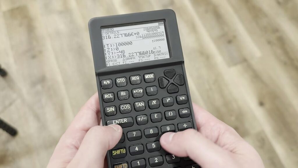
Discontinued calculators turn into collector items fast. The HP 35s left shelves in 2021 and used units soon sold above $200, which is more than a nice STM32 dev kit, a display and a PCB order combined. Inevati Systems answered by designing a replacement from a blank KiCad schematic.
What Inevati Systems built
The result is a scientific and graphing calculator with both Reverse Polish Notation and regular algebraic entry. It does graphing, matrix math and equation solving. The brain is an STM32L431, and the screen is a 400×240 Sharp Memory LCD. That display keeps its pixels without constant refreshing, so the plotting screen costs almost nothing to hold on. The full write-up is on Hackster.
The technical details worth stealing
- Power: two CR2032 cells in parallel give a 3 V supply with more capacity. Separate boost converters make 3.3 V for the logic and 5 V for the display. The STM32L431 sleeps in Stop2 mode, and the creator says that is frugal enough for years on those coin cells.
- Keyboard: 43 keys in a matrix, each with its own anti-ghosting diode so two keys pressed together still register correctly.
- PCB: 1.0 mm thick instead of the usual 1.6 mm, to keep the body slim.
- Enclosure: modeled in Fusion from STEP files exported out of KiCad, so every mounting hole lined up before anything was manufactured.
The gotchas are honest ones. Flux left under the key switches caused intermittent presses, the keycaps wobbled more than expected, and surface-mount diodes on the front of the board fought with the case. Cleaning flux with isopropyl alcohol after soldering is a cheap habit that would have saved a debugging session.
Build it yourself
You do not need 43 keys to learn from this. Start with a 4×4 keypad on a breadboard, add one diode per key, and scan rows and columns in code until you can read two simultaneous presses. Then put a Memory LCD on the SPI pins and print a number. A thesis group could stretch that into a small RPN calculator over a semester. For parts, browse the Circuit.Rocks catalog for a 4×4 membrane keypad, usually under PHP 100, and a 3.3 V STM32 or ESP32 board to run it on.
Frequently Asked Questions
Which microcontroller does this calculator use?
An STM32L431, chosen for its processing power, memory, peripherals and low sleep current. Its Stop2 mode keeps idle drain tiny.
What does it take to build a similar calculator?
A microcontroller board, a Memory LCD, a 43-key matrix with one diode per key, boost converters for 3.3 V and 5 V, and a custom PCB. The keycaps and enclosure took the most work.
What will I learn if I build this?
Keypad matrix scanning, anti-ghosting diodes, SPI display drivers, low-power sleep modes, boost converter rails and KiCad to enclosure workflow. Good thesis material for ECE students.
