
Parts list first, because this one is more doable than it looks. You need a copper plate at least 6 mm thick (Rogers used 6.35 mm), two brushless outrunner motors with matching ESCs, 24 N52 neodymium magnets, an ESP32 dev board, a buck converter that drops 22 V to 5 V, a 6-axis IMU such as the MPU-6050, and two 3S LiPo packs. The rotors that hold the magnets were 3D-printed, but a laser-cut plywood disc with glued-in magnet pockets does the same job. Budget around 1,500 pesos for the ESP32, IMU, buck module and two ESCs at circuit.rocks; copper and magnets cost more.
What Jake Rogers built
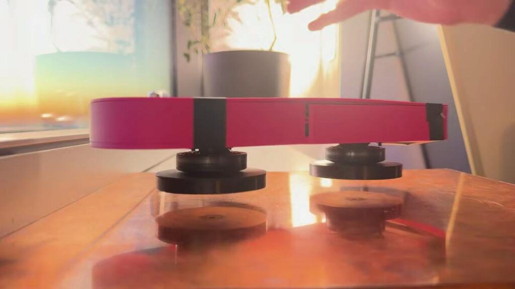
YouTuber Jake Rogers wants a hoverboard you can stand on. The prototype he has so far is a tabletop platform that floats over a copper sheet with no wheels, no propellers and no cable. The lift comes from eddy currents. Spin a ring of permanent magnets close to a conductor and the changing field induces circulating currents in the copper; those currents make their own field that pushes back on the magnets. At 4,000 RPM, a 12-magnet Halbach rotor produces roughly 4.3 N of lift at an 8 mm gap, which is enough to float a light frame. His first single-motor test lifted, then spun the whole chassis in circles, because the reaction torque from the motor had nowhere to go.
The gotchas that shaped the final board
The fix for the spinning chassis was a second motor with its own magnet rotor turning the opposite way, so the two torques cancel. The tricky part was that both ESCs shipped spinning the same direction, and swapping any two of the three motor phase wires on one ESC reversed it. Cutting the cord was the next job. The ESP32 originally ran off USB from a laptop, so Rogers added a buck converter on the 5 V rail, an IMU to report pitch and roll over I2C (SDA and SCL on GPIO21 and GPIO22 on most ESP32 boards), and Wi-Fi so he could send throttle commands and flash firmware over the air. Two 3S LiPos in series give 22.2 V nominal to the ESCs. The extra battery mass killed the lift margin at first, and the early fix was dead batteries as counterweights, until a redesigned chassis put the live packs between the two motors and balanced the load.
Where this goes next
The platform now floats on its own batteries, but only over copper, and a rideable version needs far more rotor area. That makes it a near-perfect physics-plus-embedded thesis: the Lenz’s-law lift is measurable with a kitchen scale under the plate, the ESC control is a 50 Hz servo-style PWM signal you can generate with the ESP32 LEDC peripheral, and the IMU gives you a closed-loop balance problem to solve. Watch the full build on Jake Rogers’ YouTube video, read the Hackster summary here, and if your motor only twitches, check that the ESC calibrated its throttle range before you blame the code.
Frequently Asked Questions
How does the hoverboard float without an electromagnet?
Spinning permanent magnets over a copper plate induces eddy currents in the copper. Those currents create an opposing magnetic field that repels the rotor. At about 4,000 RPM, a 12-magnet Halbach rotor gives roughly 4.3 N of lift at an 8 mm gap. It only works over a conductive surface such as copper or aluminium.
Why does it need two motors instead of one?
A single spinning rotor produces reaction torque that twists the whole chassis. A second rotor spinning in the opposite direction cancels most of that torque. Both ESCs must be set to opposite rotation, which you do by swapping any two of the three motor phase wires on one of them.
What will I learn if I build this?
You will measure Lenz’s law and eddy-current lift with real hardware, learn how brushless ESCs are driven from an ESP32 PWM output, read an IMU over I2C, wire a buck converter and series LiPo pack safely, and use Wi-Fi over-the-air firmware updates. The balance problem is a solid control-systems capstone.
