
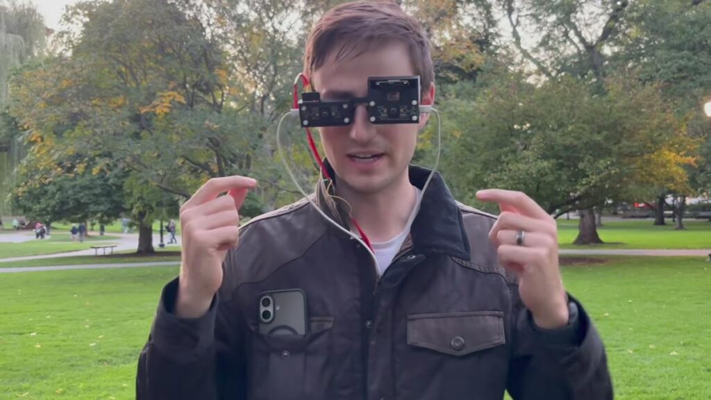
Sensory substitution is having a moment. Cheap multizone time-of-flight chips, the same parts that let a robot vacuum dodge a chair leg, now cost a few hundred pesos, and makers are strapping them to the human body to replace one sense with another. Haptic belts, ultrasonic canes, headsets that read out distances: the hardware finally fits in a pocket. DebackTech’s LiDAR smart glasses and vibrating shirt belong to that wave, and the build is a clean example of how far a Raspberry Pi and a bag of motors can take the idea.
The build
The goal was spatial awareness without cameras or audio cues. DebackTech started with a 64-zone LiDAR array, the class of part ST’s VL53L5CX belongs to, and found the resolution too coarse to tell a lamppost from a wall. The fix was a 512-zone sensor, three of them mounted across the frame of a pair of glasses, plus an IMU to track where the head is pointing. All of it feeds a Raspberry Pi 4 over the sensor bus. On the output side sits a shirt with 16 vibration motors spread around the torso. Each motor owns a slice of the surroundings, and its PWM duty cycle rises as an obstacle gets closer. The motor drivers are hand-built on protoboard, since a Pi GPIO pin cannot source the 60 to 100 mA a coin motor pulls; each channel needs a transistor, a flyback diode and a separate 5 V rail.
Technical takeaway
Two problems showed up in the Boston street tests. First, sunlight. Infrared ToF sensors see the sun as a wall of noise, so DebackTech wrote a filter that drops readings with low signal confidence before they reach the motors. Second, frame rate. The sensors deliver roughly 13 frames per second, which is fine for a slow walk and useless for an electric scooter or a thrown ball. Blindfolded catch only worked once a trajectory predictor extrapolated the ball’s path from its first few detections and fired the motors early. Crowded sidewalks exposed a third issue: too many close objects light up too many motors at once, and the pattern turns to mush. Haptic bandwidth, not sensor range, is the real ceiling on this kind of device.
What to try next
A student version of this is well within reach for a capstone group. Start with one VL53L5CX breakout on I2C (address 0x29, 3.3 V logic, pull-ups usually on the module) and a Raspberry Pi 4 or even a Pico. Map the 8×8 grid to four motors on a wristband driven through a ULN2803 or four 2N2222 transistors. Add a PCA9685 if you run out of hardware PWM pins. Once the wristband works, graduate to a chest array and log raw frames in direct sunlight versus under a roof to see the noise problem for yourself. The full video and the Hackster write-up are at hackster.io; watch the catch-the-ball segment first, because the trajectory predictor is the clever part.
Frequently Asked Questions
How do the smart glasses sense obstacles without a camera?
Three 512-zone time-of-flight LiDAR arrays on the glasses measure distance in a grid, an IMU tracks head orientation, and a Raspberry Pi 4 maps each region of the scene to one of 16 vibration motors on a shirt. Closer objects produce stronger vibration.
What were the biggest limitations in testing?
Sunlight added noise to the infrared readings until a confidence filter was added, the sensors only ran at about 13 frames per second, and crowded streets triggered too many motors at once. Catching a ball needed a trajectory prediction algorithm to compensate for the slow frame rate.
What will I learn if I build this?
Reading multizone ToF sensors over I2C, driving vibration motors safely with transistors and a separate supply, PWM intensity mapping, filtering noisy sensor data, and the human-factors side of haptic feedback design, which is a strong thesis topic in itself.
