
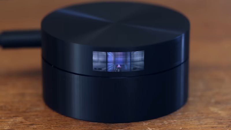
Want a weekend build that turns five LEDs and a spinning disk into a working video screen? Here’s the shopping list before anything else: a Raspberry Pi Pico, one small stepper motor, an A4988 stepper driver to run it, five LEDs (four white and one RGB), and a disk you can drill 20 tiny pin holes into. That’s the whole bill of materials for a modern mechanical television, and it costs less than most people spend on lunch for a week.
What the Scanwheel actually is
Maker James Brown, who goes by “Ancient,” rebuilt a 1920s idea with parts you can buy today. Early mechanical TVs used a spinning perforated disk (a Nipkow disk) to scan an image line by line. His Scanwheel does the same thing, except the Pico handles the timing that used to need finicky electromechanical gear. The LEDs stay fixed in the center behind dividers that stop light from bleeding between them. The disk spins in front, and light only escapes through the pin holes.
How 5 LEDs paint 20 rows
The clever part is the pin-hole spiral. There are 20 holes arranged around the circumference, each one slightly offset in radius. When the top hole sweeps past an LED, the Pico blinks that LED to draw the top row of pixels. When the next hole passes, it draws the second row, and so on down all 20 rows. That gives you a 20-pixel-tall image from a single LED. Horizontal resolution isn’t fixed at all, it’s a function of spin speed and how fast you can modulate the GPIO pins, which is why the width reads as “??? x 20.” This is persistence of vision doing the heavy lifting: the LEDs switch far faster than your eye can follow, so the rows fuse into one solid picture. The A4988 driver keeps the stepper spinning at a steady rate so the timing stays locked. Four of the five LEDs are white; only the center one is RGB, so color lives in a single channel.
Why it’s worth a Sunday
The best detail is how it scales. Want more resolution? Make the wheel bigger and drill more pin holes. Nothing in the code changes conceptually, you just add more rows to the scan loop. For an ECE or robotics student, this is a compact lesson in stepper control, interrupt timing, and how displays actually work under the hood, all for the price of a Pico and a handful of LEDs. Full build notes and video are on the Hackster writeup. Grab a Pico from circuit.rocks and start drilling.
Frequently Asked Questions
What controls the LEDs and motor in the Scanwheel?
A Raspberry Pi Pico modulates the five LEDs while an A4988 driver spins a small stepper motor. The Pico syncs LED blinks to each pin hole as it passes.
How does 5 LEDs produce a 20-pixel-tall image?
The spinning disk has 20 pin holes in a spiral. Each hole passes an LED at a different height, so one LED draws all 20 rows in sequence as the disk turns.
What will I learn if I build this?
You practice stepper motor control with an A4988 driver, precise GPIO timing on the Pico, and the persistence-of-vision principle behind how displays actually form an image.
