
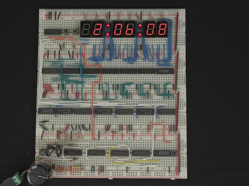
Most clock projects begin with a tiny quartz crystal soldered near a microcontroller. In his latest video, Ben Eater ignored that habit, glanced at the power outlet on his wall, and decided the electrical grid could keep better time than anything on his breadboard.
The build is a digital clock made entirely from logic chips, no microcontroller anywhere. Counting seconds, minutes, and hours is the easy part. The hard part is the heartbeat underneath it: a signal that fires once per second, every second, without drifting. Instead of a crystal oscillator, Eater pulls that rhythm from the 60 Hz alternating current that utilities in the United States hold to a very tight tolerance, which turns every wall socket into a surprisingly accurate time reference.
How the signal gets built
The same wall supply has to power the logic too, so Eater starts safely. A wall adapter steps 120 V mains down to 12 V AC, a bridge rectifier turns that into pulsating DC, and a chunky 10,000 uF electrolytic capacitor flattens most of the ripple. An LM7805 regulator then locks the rail at the 5 V the chips expect, with 0.1 uF decoupling capacitors nearby to soak up high-frequency noise.
Getting a clean 60 Hz square wave out of that messy sine takes a few more parts:
- A pair of 47 kΩ resistors scale the 12 V AC waveform down to logic levels, with a 0.1 uF cap filtering noise.
- Another 47 kΩ pair between 5 V and ground sets a 2.5 V reference.
- An LM339 comparator flips state each time the AC signal crosses that reference, and a 4.7 kΩ pull-up lifts its open-collector output to a full 5 V.
The gotcha on the oscilloscope
On paper it worked. On the oscilloscope it didn’t. Right at the 2.5 V crossing, tiny bits of noise made the comparator chatter, bouncing between high and low several times per transition. For a circuit that counts edges to tell time, those false pulses would wreck the count fast. Eater’s fix is one resistor: a 100 kΩ feedback path from the output back to the reference input adds hysteresis, so the signal has to swing well past the threshold before the output can flip again. The chatter disappears.
What you walk away with is a real lesson in rectification, voltage regulation, comparators, and why hysteresis exists, all things a thesis or classroom electronics project rarely explains this cleanly. Ben Eater sells a full kit for $99.99 if you want the exact parts, but the concept costs almost nothing to prototype on a spare breadboard. Watch the teardown of the timing stage here: Ben Eater’s AC-timed clock on Hackster.
Frequently Asked Questions
How does Ben Eater’s clock keep accurate time without a crystal?
It uses the 60 Hz frequency of US AC mains power as its timing reference. Utilities hold that frequency to a tight tolerance, so an LM339 comparator turns the AC sine into a clean 60 Hz square wave the counter chain can divide down to one pulse per second.
Why does the circuit need a 100 kΩ feedback resistor?
Without it, electrical noise near the 2.5 V comparator threshold makes the output chatter and fire false edges. The 100 kΩ feedback adds hysteresis, forcing the signal to swing well past the threshold before switching, which cleans up the timing pulse.
What will I learn if I build this?
You’ll get hands-on practice with rectification, using an LM7805 to make a regulated 5 V rail, reading a signal on an oscilloscope, and designing comparator hysteresis. Those are core analog and digital skills that carry straight into thesis and capstone electronics work.
