
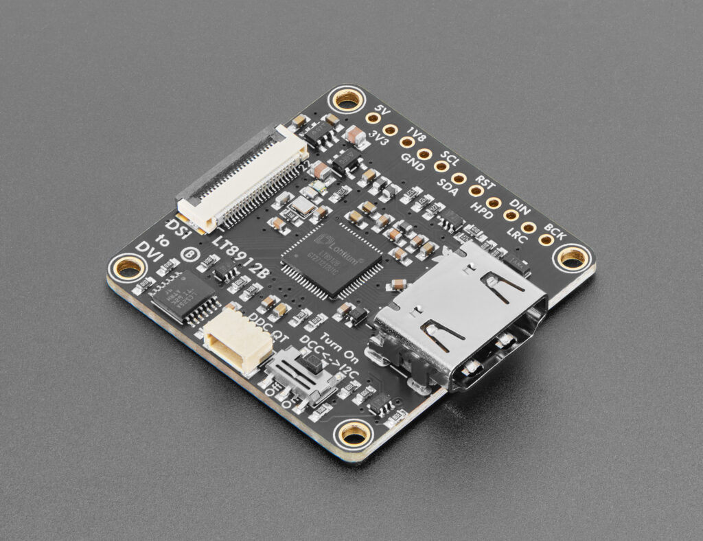
Your SPI TFT tops out around 320×480 pixels, and a parallel TTL panel eats 30+ GPIO pins. Adafruit’s new LT8912B board skips both problems by taking a DSI display signal and turning it into DVI/HDMI, so a Raspberry Pi 5 or ESP32-P4 can drive an ordinary monitor or TV.
What the board does
DSI is the MIPI high-speed serial display link already found on Raspberry Pi boards and, now, the ESP32-P4. The Adafruit LT8912B converter accepts up to 4 lanes and outputs as high as 1080p60. You can even feed the HDMI side into a capture dongle and pipe the picture into a computer.
Wiring and setup details
The input side has a 22-pin, 0.5 mm pitch FPC connector that matches the Raspberry Pi 5 pinout. An older Pi with the 15-pin, 1 mm pitch connector needs an adapter flex cable, and the board ships without one, so order the right cable separately. That is the first gotcha: the wrong cable means a blank screen.
The second step is configuration. The LT8912B is set up over I2C, and the FPC cable carries the SDA and SCL lines, so no extra wires are needed. Adafruit provides Arduino and CircuitPython libraries for the microcontroller route. On a Raspberry Pi there is a kernel module, and a device tree overlay sets the chip resolution. Match the resolution to the DSI output and to what your monitor accepts, or you will get no signal.
Build it yourself
Start on a Raspberry Pi 5 with a spare HDMI monitor: connect the FPC cable, enable the overlay, and check that the display comes up at 1920×1080. For a school robotics team, this makes a cheap way to show a live camera feed or dashboard on a classroom TV. For a thesis project on an ESP32-P4 board, you get a full-size display without 30 wires. Read the product page at blog.adafruit.com for the exact driver links, then check circuit.rocks for Raspberry Pi 5 stock and cables.
Frequently Asked Questions
What does the LT8912B converter do?
It converts a MIPI DSI display signal, up to 4 lanes, into DVI/HDMI output at up to 1080p60, so DSI-capable boards can drive standard monitors and TVs.
Which cable do I need to connect it?
The board has a 22-pin 0.5 mm FPC input matching the Raspberry Pi 5 pinout. Older Pis with a 15-pin 1 mm connector need an adapter cable, which is sold separately.
What will I learn if I build this?
You learn how DSI differs from SPI and parallel displays, how to configure a chip over I2C, and how device tree overlays set up display hardware on Linux.
