
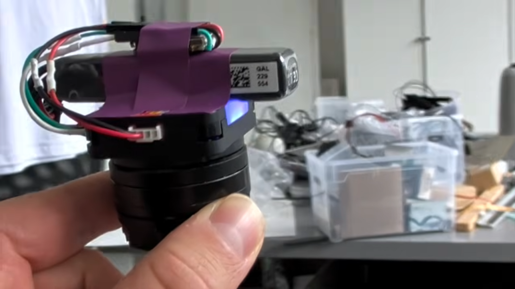
Hold the thing in your palm, twist your wrist, and the little motor on top twists back the same amount, so the arrow on its OLED keeps pointing at the window. Spin a full turn on your heels and it still points at the window. That is the whole demo of cpietsch’s CAN do GYRO, and a minute of feeling it fight your hand explains closed-loop control better than a semester of block diagrams.
What they built
It is a one-axis gimbal made from two off-the-shelf parts. On top is an M5Stack Unit RollerCAN: a D3504 gimbal brushless motor with a magnetic encoder, a DRV8311 field-oriented-control driver, its own STM32G431 and a small OLED, talking CAN over an XT30 plug that also carries 6 to 16 V. Underneath sits a Seeed XIAO STM32C5, picked because its STM32C5A3CG has two FDCAN controllers and the board already carries a TCAN3403 transceiver with 120-ohm termination, plus an LSM6DS3TR-C six-axis IMU on I2C. A 2S LiHV pack of 580 mAh powers both. The wiring is four soldered pigtails: CANH, CANL, 5 V and ground. Code, log tools and a long README are at github.com/cpietsch/can-do-gyro, with the demo at youtu.be/w_WODAGTqgk.
How they built it
The firmware is C on Zephyr (no Arduino core exists for the STM32C5 yet), built with PlatformIO. The main loop runs about every 1 ms: read the gyro from the IMU FIFO at 416 Hz, integrate it into a quaternion, nudge the tilt toward gravity whenever the accelerometer reads close to 1 g, then send one classic CAN 2.0 frame at 1 Mbit/s to the RollerCAN with a new target position. There is no PID in the XIAO. The target is simply the current rotor angle minus the measured deviation, plus a damping term (100 ms of turning rate) and a slow integral with a 4 s time constant; the motor’s own position controller does the pushing, with stiffness set to 15 mA per degree and current capped at 500 mA. Two gotchas from the README: the IMU is heated to 40 degrees C by a PI loop on PA8 so the gyro offset stops drifting, and a loop faster than 1 ms made the orientation estimate run away for reasons the author still has not pinned down. The motor also cuts out if the rotor swings more than 180 degrees in 0.2 s, and it shuts down at 3.50 V per cell.
Takeaway
Ten years ago a DIY gimbal meant building your own driver and tuning FOC by hand. Now the motor ships with the driver, the encoder and the control loop inside, and your job shrinks to sensor fusion and one CAN message per millisecond. That makes this a realistic one-week capstone sub-project for an ECE team: the tuning numbers are documented and the serial console lets you change stiffness and damping live. Grab a XIAO STM32C5 and a RollerCAN, clone the repo, and try changing POSITION_KP from 15 to 25 to feel the loop start to buzz at 50 Hz.
Frequently Asked Questions
How does the CAN do GYRO know which way it is pointing?
An LSM6DS3TR-C six-axis IMU on the XIAO STM32C5 streams gyro data at 416 Hz. The firmware integrates it into a quaternion and corrects the tilt toward gravity whenever the accelerometer reads about 1 g, a Mahony-style filter with a 2 s time constant. Every millisecond it sends the RollerCAN a new position target so the rotor turns against the measured rotation, keeping the top pointed the same way.
What parts do I need and roughly what do they cost?
A Seeed XIAO STM32C5 (on-board IMU and CAN transceiver included), an M5Stack Unit RollerCAN motor, a 2S LiPo or LiHV pack with an XT30 plug and four short wires. Expect about PHP 1,200 for the XIAO and PHP 2,500 to 3,000 for the RollerCAN imported. Firmware is C on Zephyr built with PlatformIO, so you also need a laptop with a USB-C cable; no debugger is required because the board boots into UF2.
What will I learn if I build this?
You will learn sensor fusion from raw gyro and accelerometer data, how CAN bus framing and bitrates work in practice, how a smart motor with built-in FOC exposes a position target over a network, and how to tune a control loop by changing stiffness, damping and integral terms while watching the result in your hand. It is a compact way to cover the control-systems and embedded-networking topics in an ECE syllabus with one physical demo.
