
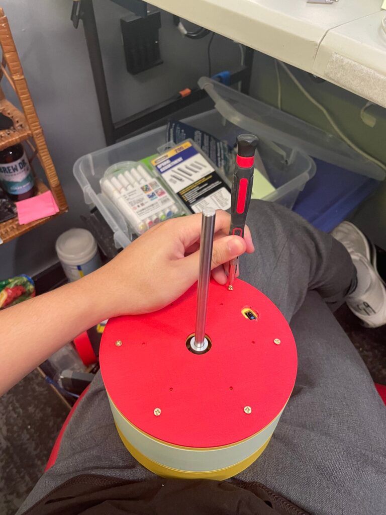
Parts first. Thomas Vu Nguyen’s PicoCentrifuge needs a Raspberry Pi Pico, an A2212/1000KV brushless drone motor, a 30 A sensorless ESC, a 2S LiPo (about 7.4 V) with a fuse and a physical disconnect, a 5-to-8 mm aluminum coupler, an 8 mm steel rod on bearings, an IR reflective sensor for the tachometer, an MPU-6050 for vibration sensing, and a four-arm rotor printed in PETG. Total: roughly $50, or around PHP 3,000. A used lab centrifuge that fits 15 mL conical tubes goes for $800 to $3,000 on eBay.
Why a maker built a centrifuge
The build is one piece of Bloom, an open-source cancer-immunotherapy pipeline Thomas is developing in public after losing his mother to cancer. Its software predicts which peptides might trigger an immune response; proving it takes a wet lab, and step one is spinning blood over a Ficoll density gradient at about 400 × g for 30 minutes to pull out the PBMC layer. Existing printed centrifuges like OpenFuge mostly can’t hold 15 mL conicals, so he designed a fixed-angle rotor in Onshape that does. A first attempt drafted by an AI agent in Fusion 360 called for a 466 mm containment vessel, stock-pot sized, and was scrapped.
The electronics underneath
The Pico drives the ESC with a 50 Hz servo-style PWM signal on GPIO1: 1000 µs to arm, then a ramp from 1060 to 1300 µs in 20 µs steps every two seconds. The MicroPython test script is about 20 lines of machine.PWM and time. The ESC has brake disabled and a smooth ramp programmed, because hard-braking a centrifuge wrecks the gradient you just spent half an hour forming; coast-down takes at least two minutes. Target speed comes from rpm = sqrt(RCF / (1.118e-5 × r_cm)); the oversized first design would have needed 1,545 rpm at a 150 mm radius. Speed control is a PID loop: the IR sensor counts pulses off the rotor underside and the Pico trims throttle to hold the setpoint. The MPU-6050 bolts to the chassis near the bearing holder, not the rotor; if a tube shifts and the vibration signature changes, the Pico kills motor power. The mechanical gotcha: opposing tubes must be matched to ±0.1 g, since an imbalance at 1,500 rpm can throw a tube through a wall.
Where it stands
The drivetrain ran clean on the bench. Nothing biological goes in until a validation gate passes: fastener retention, rotor runout, balance, a deliberate imbalance shutdown, a guarded overspeed test with the lid closed, and finally dyed water over glycerol at setpoint for 30 minutes. A clean interface between the layers proves it separates by density. For a Filipino ECE or biomedical capstone, that glycerol test alone is a safe, solid project: ESC control, closed-loop PID, and an accelerometer safety interlock on a Pico from circuit.rocks. CAD is public on Onshape; BOM, build log and firmware live at github.com/ThomasVuNguyen/picocentrifuge, with the write-up at comfyspace.tech. Run the ramp script with no rotor attached first; coil whine at higher throttle is normal, not a fault.
Frequently Asked Questions
How does PicoCentrifuge hold a steady speed?
An IR reflective sensor under the rotor gives the Raspberry Pi Pico a pulse-per-revolution tach signal. The Pico runs a PID loop that trims the 50 Hz PWM throttle to the 30 A ESC until the measured RPM matches the setpoint computed from the target g-force and rotor radius, then holds it for the 30-minute run.
What does it cost and what is the hardest part?
Parts come to about $50: an A2212/1000KV drone motor, a 30 A ESC, a Pico, a 2S LiPo, an MPU-6050, an aluminum coupler, bearings and an 8 mm rod, plus printed PETG parts. The hard part is mechanical, not electrical: opposing tubes must be matched to within 0.1 g, the ESC brake must be off with a slow two-minute coast-down, and every powered test runs inside a lidded containment vessel.
What will I learn if I build this?
You will learn to drive a hobby ESC from a microcontroller with servo-style PWM in MicroPython, build a closed-loop PID speed controller from a tachometer input, use an MPU-6050 accelerometer as a vibration safety interlock, and write a validation plan that proves a machine is safe before it handles anything real. Stop at the dyed-water-over-glycerol test for a school project.
