
What you need before you start
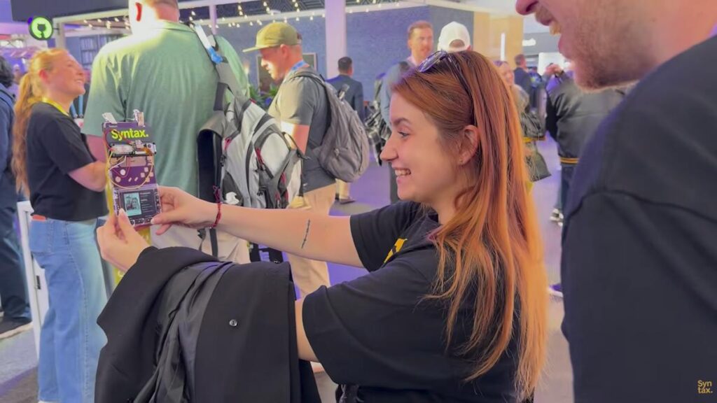
One hackable conference badge, one camera board, two bright LEDs, a pocket Bluetooth thermal printer, hookup wire and a soldering iron. That is the whole shopping list behind the photo booth web developer Wes Bos built from his GitHub Universe badge. The badge is a Pimoroni Tufty 2350: an RP2350 with 16 MB of flash and 8 MB of PSRAM, a 2.8-inch 320×240 colour IPS display, Wi-Fi plus Bluetooth 5.2, a 1,000 mAh battery and user buttons, running Pimoroni’s MicroPython-based Badgeware firmware. No badge? A Tufty 2350 sells on its own, and the recipe works on any RP2350 or RP2040 board with a screen. The receipt printer is the cheap sticker-label kind, about 10 to 15 US dollars online.
What Bos built
Bos was tired of watching AI tools write his code and wanted to make something with his hands. The badge already had a screen, buttons, an accelerometer and wireless, so the missing piece was a camera. He wired an ESP32 camera module to the badge’s I2C expansion header, soldered power and signal lines between the boards, and added a pair of LEDs as a flash. Everything runs from the badge’s own battery. A MicroPython app pulls frames from the camera, shows a live preview on the 320×240 panel, and on a button press lights the LEDs and grabs a still. A second routine dithers the capture to one-bit black and white and ships it over Bluetooth to the thermal printer, which spits out a palm-sized receipt photo.
The technical bits worth copying
Two parts of this build teach the most. First, the image pipeline: a thermal head only knows black or white, so a greyscale frame needs a dithering pass (Floyd-Steinberg or ordered Bayer) before it looks like a photo instead of a blob. Second, the hand-off between boards. Bos went wired, but Sam Meech-Ward, who appears in the same video, went Wi-Fi: his esp32-badge-video-streamer has a Seeed XIAO ESP32-S3 Sense with an OV2640 sensor host its own hotspot and stream 160×120 JPEG frames to a stock Badgeware app, no router needed. Pick wired if you want simple soldering and a shared battery; pick Wi-Fi if you would rather not match 3.3 V logic levels and I2C pull-ups by hand. The gotcha on the wired path is power: an ESP32-CAM draws spikes near 300 mA when the radio and sensor wake together, so feed it from the battery rail, not a GPIO.
Where to go from here
Installing an app on the badge is drag-and-drop: double-tap RESET, a “Tufty2350” drive appears, copy your folder into apps/ and eject. The pimoroni/tufty2350 repo has the firmware releases and the Badgeware API docs, and Bos posted his progress on X. For a classroom version without a conference badge, an ESP32-CAM board at circuit.rocks runs roughly 400 to 600 pesos, a 128×64 OLED stands in for the preview screen, and the same dither-and-print code applies. Start by printing a static bitmap; add the camera once the printer prints a clean checkerboard.
Frequently Asked Questions
How does the badge talk to the camera and the printer?
Bos soldered an ESP32 camera module to the Tufty 2350’s I2C expansion header for power and data, and sent the finished image to a cheap Bluetooth thermal printer using the badge’s built-in Bluetooth 5.2 radio. Sam Meech-Ward’s alternative streams camera frames over a Wi-Fi hotspot instead, with no wires between the boards.
What does a build like this cost without the free conference badge?
A Tufty 2350 badge is the priciest part. The pocket thermal printer runs about 10 to 15 US dollars, an ESP32-CAM board is roughly 400 to 600 pesos at circuit.rocks, and the LEDs and wire are pocket change. Swap the badge for any RP2350 or RP2040 board with a small display and the total drops sharply.
What will I learn if I build this?
MicroPython on the RP2350, pulling image frames from a camera module, converting greyscale to one-bit with a dithering algorithm, driving a Bluetooth thermal printer, wiring two boards together over I2C with shared power, and managing current spikes on a battery-powered device. It is a compact end-to-end embedded imaging project.
