
Picture a drawer full of RC parts: a loose IMU breakout, a GPS board, three jumper-wire spaghetti nests, and a flight controller that only works with one airframe. The maker known as The Engineer got tired of rebuilding that mess every project and designed a single board to replace it. Hackster News covered the build.
What The Engineer built
The board is a Pixhawk-inspired flight controller around an ESP32-S3. It pairs the chip with an SPI-connected IMU (accelerometer plus gyroscope), so the board always knows how it is tilted in 3D space. Several JST-GH connectors expose UART, I2C, and SPI, each labeled with its GPIO number, so a GPS, a LoRa radio, or a barometer plugs in without soldering new wires.
How it came together
Power gets careful treatment. Two separate 3.3 V regulators run the board: one feeds the ESP32-S3, the other feeds only the IMU so Wi-Fi bursts do not leak noise into the gyro readings. The 5 V rail comes from USB-C or a dedicated connector.
The layout was drawn in KiCad with parts on both sides of the PCB. Boards and solder paste stencils were ordered from a fab, then assembled by hand with paste and a hot plate for reflow. The plastic JST connectors were soldered separately, since they melt at reflow temperatures.
The gotcha showed up at bring-up. A damaged USB-C port stopped normal flashing, so a CP2102 USB-to-serial adapter on UART took over. MicroPython went on, and the IMU started reporting data.
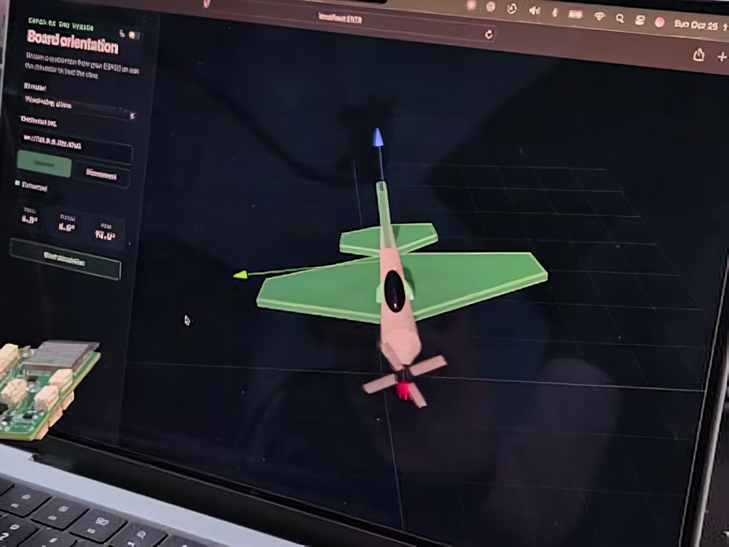
To see the result, he wrote a React app with 3D models of a plane and a drone. The ESP32-S3 joins local Wi-Fi and streams orientation over WebSockets, and the virtual aircraft tilts when the real board does.
The takeaway
No propellers have spun yet. GPS and LoRa modules are planned next. For a thesis or capstone, the useful part is the method: isolate the sensor supply, standardize connectors, and test with a visualizer before risking a flight. An ESP32-S3 dev board is a good way to rehearse the IMU and WebSocket code first, and you can find one at circuit.rocks before committing to a PCB order.
Frequently Asked Questions
What does this flight controller use for motion sensing?
An SPI-connected IMU with an accelerometer and gyroscope feeds orientation data to the ESP32-S3, which streams it over WebSockets to a React 3D visualizer.
Why does the board use two 3.3 V regulators?
One regulator powers the ESP32-S3 and supporting parts, and the other powers only the IMU to keep Wi-Fi and digital noise out of the sensor readings.
What will I learn if I build this?
You will practice KiCad PCB layout, hot plate reflow soldering, SPI sensor reads in MicroPython, UART fallback programming, and streaming data over WebSockets.
