
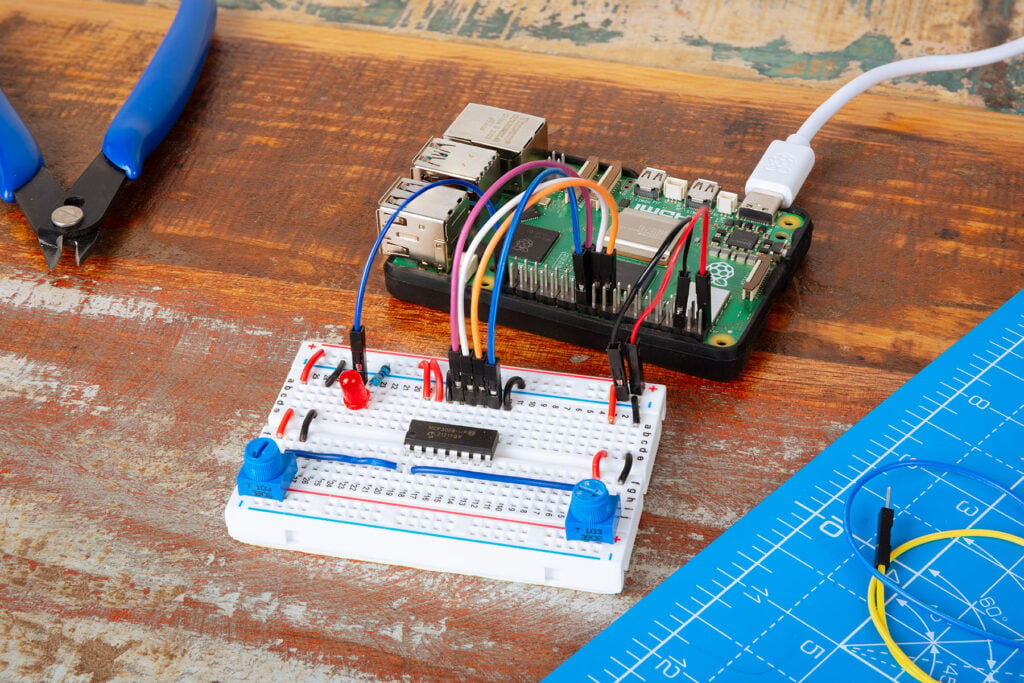
There is a specific kind of satisfaction in twisting a knob and hearing a station slide into place. That tactile feel is what this Raspberry Pi tutorial chases: two potentiometers on a breadboard, one picking the station, the other riding the volume, driving a Pi that streams internet radio through VLC.
Three projects, one circuit
The build starts small. A single potentiometer controls the brightness of an LED, so turning the knob dims it smoothly. Add a second pot and the pair set the blink rate instead. Swap the LED output for VLC and the same wiring becomes a radio, with SomaFM Groove Salad at one end of the dial and an indie pop stream at the other. Nothing on the breadboard moves between the three stages, which makes it a tidy classroom progression.
Why the MCP3008 is doing the real work
Raspberry Pi GPIO pins are digital. They read high or low and nothing between, so a potentiometer sweeping from 0V to 3.3V is invisible to them. The MCP3008 solves that. It is an 8-channel analogue-to-digital converter that hands the Pi clean readings over SPI, no capacitor timing trick required.
- Seat the chip across the central groove of the breadboard, then run its four middle legs to GPIO 8 (CE0), 10 (MOSI), 9 (MISO) and 11 (SCLK).
- Enable SPI with
sudo raspi-configunder Interface Options, and confirmpython3-spidevis installed before you reboot. - Wire each pot with its outer legs on the 3V3 and ground rails and its wiper into channel 0 or channel 1.
- In GPIO Zero,
MCP3008(channel=0)returns a float from 0 to 1, andled.source = pot.valuespipes it straight into aPWMLEDon GPIO 21.
The gotcha worth knowing
The radio script guards its station change behind an if that compares the dial position against current_station. Skip that check and VLC gets killed and relaunched on every pass of the loop, so the stream stutters instead of playing. Volume goes through wpctl, the WirePlumber command-line tool, rather than the older ALSA mixer calls you will find in most older Pi radio write-ups.
Worth a weekend
An ADC chip is the piece most beginners skip, and skipping it caps what a Pi can sense: no light sensors, no sliders, no joystick position, no analogue temperature probes. Learn the MCP3008 once and every one of those opens up. Grab the finished code from the Raspberry Pi Press GitHub repo, or read the full wiring diagrams in the original tutorial, then add a third station by adjusting the dial value thresholds.
Frequently Asked Questions
Why do you need an MCP3008 to read a potentiometer on a Raspberry Pi?
Raspberry Pi GPIO pins only read digital high or low, so they cannot see a potentiometer sweeping from 0V to 3.3V. The MCP3008 is an 8-channel analogue-to-digital converter that samples that voltage and sends the value to the Pi over SPI, giving you a clean 0 to 1 reading in GPIO Zero without any capacitor timing workaround.
What parts does this internet radio build need?
A Raspberry Pi with SPI enabled, an MCP3008 ADC, two potentiometers, an LED with a current-limiting resistor for the first stage, a breadboard and jumper wires. On the software side you need GPIO Zero, the python3-spidev package and VLC to play the M3U stream. Nothing here is exotic, and the whole bill of materials is bench-drawer stuff.
What will I learn if I build this?
You will learn how SPI works in practice, how to wire an ADC chip across a breadboard groove and map its legs to GPIO 8, 10, 9 and 11, and how to convert an analogue voltage into a usable number in Python. You also pick up PWM for LED brightness and how to control an external process like VLC from your own script. Those skills carry straight into thesis work with light sensors, sliders, joysticks and analogue temperature probes.
