
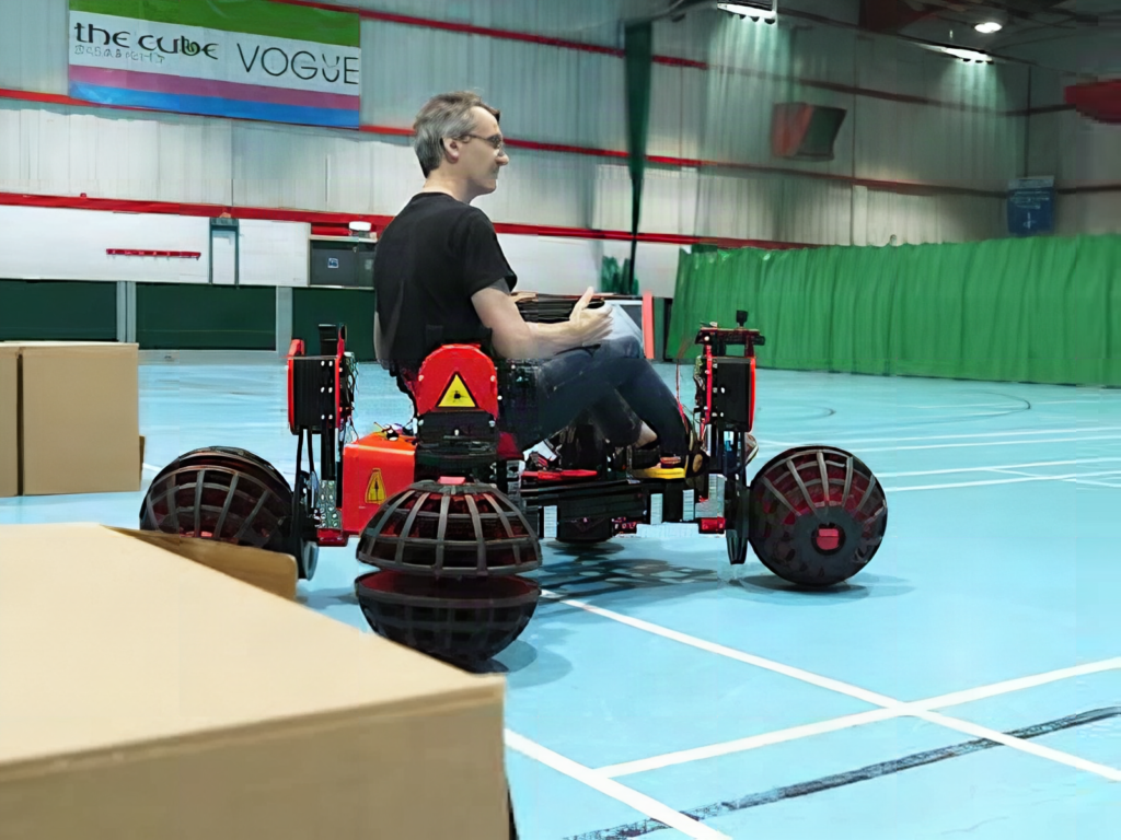
Picture a parking slot on a crowded street in Quezon City, barely a car-length long. Most drivers would shuffle back and forth three or four times. James Bruton’s newest vehicle would just slide in sideways, no steering input needed. The robotics YouTuber built a rideable electric car that moves in any direction at all, and the trick is a set of four ball-shaped wheels you will not find in any auto parts store.
What he built
The vehicle is a one-seater platform on an aluminium-extrusion chassis, sitting on four big ball-wheels mounted at 45-degree angles around the frame. Each wheel is really two hemispheres on a T-shaped axle, based on research from Osaka University. The hemispheres get driven together in one direction but roll freely in the other, so when all four motors coordinate, the car can roll forward, strafe sideways, crab diagonally, or spin in place. On top of manual joystick control it can also drive itself: two RPLIDAR S3 lidars at opposite corners give 360-degree coverage, and a ROS 2 SLAM stack builds a map and plans routes around obstacles.
How he built it
The hemispheres are mostly plywood. Bruton CNC-cut 14 vertical ribs plus a stack of horizontal layers for each one, wrapped the edge in rubber for grip, and capped the tips with 3D-printed domes hiding small skateboard wheels, so the ball keeps rolling even when the car’s weight rests on a tip. Heavy-duty bearings hold the hemispheres on the axles.
Power comes from four ODrive S1 motor kits, each rated at 2 kW, driving the wheels through two-stage belt reductions. Magnetic encoders close the loop so the four wheels agree on what “sideways” means. Four 6S LiPo packs feed 50 V to the motors, with a heavy-duty contactor and an emergency stop button in the circuit, which is the kind of gotcha you do not want to discover mid-test-drive.
The brain is Arduino’s new VENTUNO Q board. It pairs an STM32 microcontroller with a Qualcomm Linux computer: an octa-core processor, 16 GB of RAM, and an NPU rated at 40 TOPS. The STM32 handles the low-level jobs, reading a three-axis joystick and talking to the motor controllers over CAN bus, while the Linux side runs ROS 2 for navigation. That split is a pattern worth copying: real-time motor I/O on a microcontroller, perception and planning on Linux, and a well-defined bus between them.
The takeaway for your own builds
You do not need 8 kW of motor to borrow the ideas here. A tabletop version with four small DC gearmotors, one encoder per wheel, and an Arduino Nano reading a joystick teaches the same kinematics: each wheel’s speed is a mix of the X, Y, and rotation commands, and the 45-degree mounting is what makes the math clean. The CAN bus between microcontroller and motor controllers is also a good first industrial protocol for ECE students who have only used I2C and UART so far. Watch Bruton’s video and read the full write-up at Hackster, then sketch what a half-metre version would need on your bench.
Frequently Asked Questions
How do the ball-wheels let the car move sideways?
Each wheel is two hemispheres on a T-shaped axle that are driven in one direction but roll freely in the perpendicular one. With four wheels set at 45-degree angles, mixing the motor speeds produces motion in any direction, including pure sideways travel and spinning on the spot.
What are the main parts, and what skills does the build need?
Four 2 kW ODrive S1 motor kits with magnetic encoders, four 6S LiPo packs (50 V total), two RPLIDAR S3 sensors, an Arduino VENTUNO Q, and CNC-cut plywood hemispheres on an aluminium-extrusion frame. You need CNC or woodworking access, comfort with CAN bus and motor tuning, and some ROS 2 experience for the autonomous part.
What will I learn if I build a smaller version?
Omnidirectional kinematics (turning X, Y and rotation commands into per-wheel speeds), closed-loop motor control with encoders, splitting a robot between a real-time microcontroller and a Linux computer, CAN bus communication, and the basics of lidar SLAM in ROS 2. All of that maps directly onto robotics competitions and capstone projects.
