
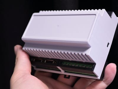
Is a $1,000 Allen-Bradley PLC actually worth a hundred times what an equivalent dev board costs, or is industrial automation just charging what the market will bear?
Clem Mayer of element14 Presents went looking for a real answer instead of a forum opinion. A programmable logic controller is, stripped down, an I/O box: read a temperature sensor, fire a hydraulic pump, reverse it when force crosses a threshold. Any microcontroller board handles that logic for under $10. So Mayer built his own PLC and kept a running tally of everything he had to add before the thing deserved the name.
What the extra $990 actually buys
He started with a BeagleBoard PocketBeagle 2 and its TI AM6254 SoC, picked specifically for the two PRUs (programmable realtime units) baked into it. PRUs run independently of the main Cortex cores, so timing-critical I/O never gets stepped on by the Linux scheduler. Then came the carrier board, which is where the cost story lives:
- Four relays for switching external loads
- Optocouplers between each relay and the processor, so a fault on the mains side has no conductor path back to the logic
- ESD protection on the exposed field pins
- Over-current protection on every output
None of that shows up on a $10 board, and all of it is the gap between a prototype and something that runs a heat press for ten years.
Mayer’s test rig was a color-detection setup: a webcam feeding OpenCV, analog thresholds selecting a target color, a detection overlay streamed over the network. Modest work for a PLC sitting on a bench. Real ones sit in 50 degrees C of plant heat under constant vibration for a decade. That gap is most of the markup, and Mayer landed on the same conclusion the vague forum answers point at, only with receipts.
Try it on your own bench
If you are scoping a capstone on industrial control, this is a cheaper path than begging a plant for a loaner PLC. Start with the isolation stage rather than the logic: wire one relay through an optocoupler on a breadboard and confirm your GPIO can switch it with no ground bounce showing on the scope. The tricky boundary is always 24 V field side to 3.3 V logic side, and that is the part a $10 board quietly ignores. Full build notes are on hackster.io.
Frequently Asked Questions
What board is this DIY PLC built on?
A BeagleBoard PocketBeagle 2, chosen for its TI AM6254 SoC. That chip carries two PRUs (programmable realtime units) that run separately from the main Cortex cores, so timing-critical I/O is not at the mercy of the Linux scheduler. Everything else sits on a custom carrier board.
Why does the build need optocouplers if the relays already switch the load?
Relays switch the load, but their coils and contacts still share a physical conductor path with the board. An optocoupler breaks that path with light instead of copper, so a mains-side fault or an inductive kick cannot travel back into the processor. Add ESD protection on the field pins and over-current protection on each output and you have most of the price difference against a bare dev board.
What will I learn if I build this?
Galvanic isolation, relay driving, and protection design, which are the parts of industrial control that classroom PLC labs usually hide behind a sealed enclosure. You also get practice laying out a two-layer carrier board around an SBC, reading a SoC datasheet for realtime peripherals, and wiring a 24 V field side safely to 3.3 V logic. That mix reads well on an ECE capstone or an automation internship application.
