
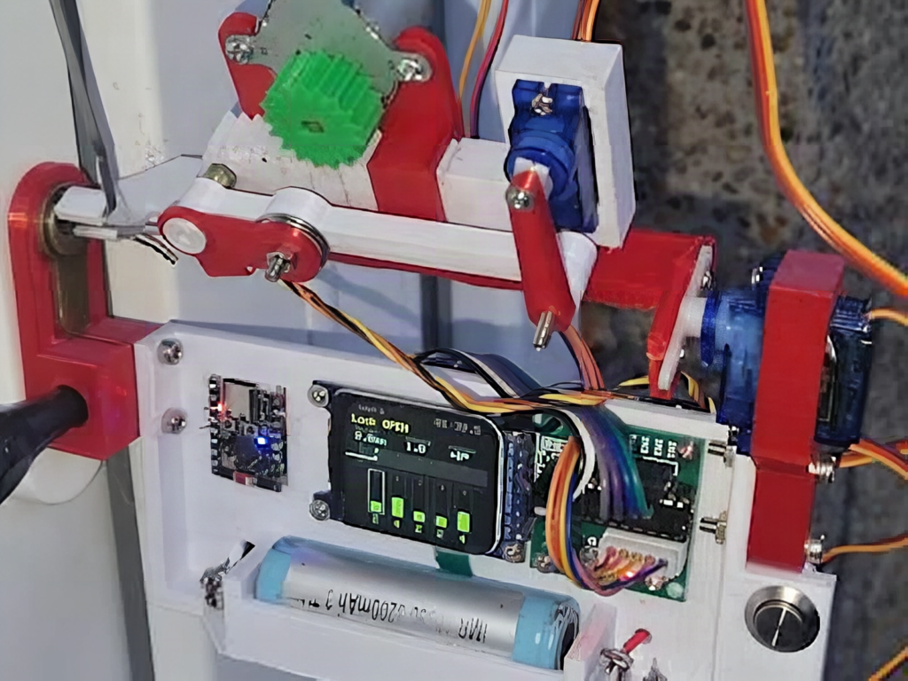
A robot that feels a lock’s pins through load cells and asks a cloud AI what to do next is a tidy lesson in closed-loop control. Dr. Kun Dániel built exactly that, and Hackster covered it in this write-up.
Why the build matters for learners
Most student robots run a fixed script: move 90 degrees, wait, repeat. This one reads force, decides, and adjusts, which is the jump from “it moves” to “it senses.” The same loop shows up in thesis work on robotic grippers, balance bots, and quality-inspection rigs. Treat it as a locksport and mechanism study, and only ever practice on locks you own.
What was built
The machine clamps onto a door’s lock cylinder and probes the pin tumblers one at a time. An ESP32-C3 Mini board handles local control and talks to Anthropic’s Claude over Wi-Fi, sending force readings and receiving guidance on the next move. The mechanics are small: 1 stepper motor, 2 servos, and 2 load cells, with a lithium-ion cell for power and an OLED showing status and pin measurements. Dániel reports more than 200 hours of work so far and plans to release the source code, STL files, and documentation once the build is reliable.
Technical details
The clever part is the feedback path. Load cells output only a few millivolts, so they normally sit behind an amplifier such as the HX711 before the ESP32 reads them over two GPIO pins. A rack-and-pinion converts the stepper’s rotation into the straight-line push the pick needs, and the servos handle tension. The tricky gotcha is latency: a Wi-Fi round trip to a cloud model takes far longer than a local loop, so time-critical safety limits, like a force ceiling that stops the stepper, belong in the firmware on the ESP32 itself.
Build it yourself
You do not need a lock to learn from this. Wire one load cell and an HX711 to an ESP32 (3.3 V supply, one data pin, one clock pin), print a few grams of known weight, and log the raw readings over serial. Then add a servo that presses on the cell and stop it when the reading crosses a threshold you choose. That is the whole sense-decide-act loop in about 40 lines of code. Check the original project details on Hackster and watch the creator’s channel for the release.
Frequently Asked Questions
What hardware does the lockpicking robot use?
An ESP32-C3 Mini board, 1 stepper motor, 2 servo motors, 2 load cells, an OLED display, and a lithium-ion battery. Most of the chassis and the rack-and-pinion are 3D printed.
How does the robot decide how to move?
Load cells measure the force on each pin. The ESP32 sends those readings to Claude over Wi-Fi, and the reply guides the next probing move, instead of following a fixed script.
What will I learn if I build this?
You will learn load cell wiring and amplifier basics, servo and stepper control, closed-loop feedback, and why safety limits belong in local firmware rather than behind a Wi-Fi API call, all useful for robotics thesis projects.
