
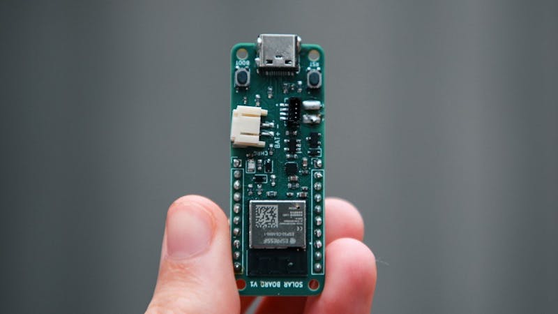
Want a sensor node you drop in the garden and forget about? Here’s the shopping list for a build-it-yourself take on Andrei Pokotylo’s Solar Devboard V1: an ESP32-C6 module, a Texas Instruments BQ25186 charging IC, a small lithium cell on a JST connector, a solar panel rated up to 18 V, and a Qwiic connector so you can bolt on I2C sensors without soldering. Add a USB-C port for flashing and reverse-polarity protection on the solar input, and you have a node that tops up its own battery whenever the sun is out.
What the board actually does
Most remote sensor projects die the same way: the battery drains, and nobody wants to hike out to swap it. Pokotylo’s answer puts the whole solar-charging circuit on the main board instead of bolting on a separate charger module. The result is a Raspberry Pi Pico-sized board that keeps a battery alive from sunlight alone, while still breaking out ten GPIO pins for whatever you want to wire up. It is a clean fit for a mesh of outdoor nodes reporting soil moisture, temperature, or door states back to a hub.
The parts that make it work
The choice of the ESP32-C6 is the first smart move. Instead of a Wi-Fi-only variant, the C6 also speaks Zigbee and Matter-over-Thread, both far kinder to a battery than constant Wi-Fi chatter. Charging is handled by the BQ25186, which accepts up to 18 V from a panel and includes power-path management, so the board can run straight off the solar cell when there is enough light and spare the battery a charge cycle. That power-path trick is the gotcha most cheap charger modules miss, and it is why they cook a battery under a fluctuating panel voltage. A torn USB-C pad during assembly got rescued with a single jumper wire, a reminder that reflow soldering surface-mount connectors is fiddly work.
Try it this way
The field test is the useful lesson. Running ESPHome over plain Wi-Fi and waking every 10 minutes, the small panel could not keep up and the battery flatlined inside a day. Stretch the wake interval to one hour and the Home Assistant logs showed the voltage dipping overnight and climbing again once the morning sun hit the panel. So size your duty cycle to your panel, not the other way around. You can read the full build write-up on Hackster or grab a board from PCBWay. Sourcing an ESP32-C6, a BQ25186, and Qwiic sensors for your own version? Those parts are on the shelf at circuit.rocks.
Frequently Asked Questions
How does the Solar Devboard V1 charge without a separate charger module?
The Texas Instruments BQ25186 charging IC is built onto the main board. It accepts solar input up to 18 V and uses power-path management to run the board directly from the panel when light is strong, only cycling the lithium battery when needed.
Why use the ESP32-C6 instead of a regular Wi-Fi ESP32?
The C6 supports Zigbee and Matter-over-Thread on top of Wi-Fi. Those low-power mesh protocols draw far less energy than constant Wi-Fi transmissions, which matters a lot when a small solar panel is your only power source.
What will I learn if I build this?
You will practice reading a battery-charger datasheet, laying out a PCB with power-path management, reflow soldering surface-mount parts like a USB-C connector, and tuning a sensor’s wake interval against a real solar power budget using ESPHome and Home Assistant.
